
Iot Garagedoor Opener
A friend came to me and told me about his garage box problem. He owns garageboxes that are centrally accessible through a main entry which is controlled by a single garage door. This door is open during the day and closes in the evening until 6 AM in the morning for security reasons. Not every owner of a garage box has a remote control so sometimes it happens those persons call him to open the main gate when they need to get to their car.
That’s where this project started to build an internet connected garage door opener.
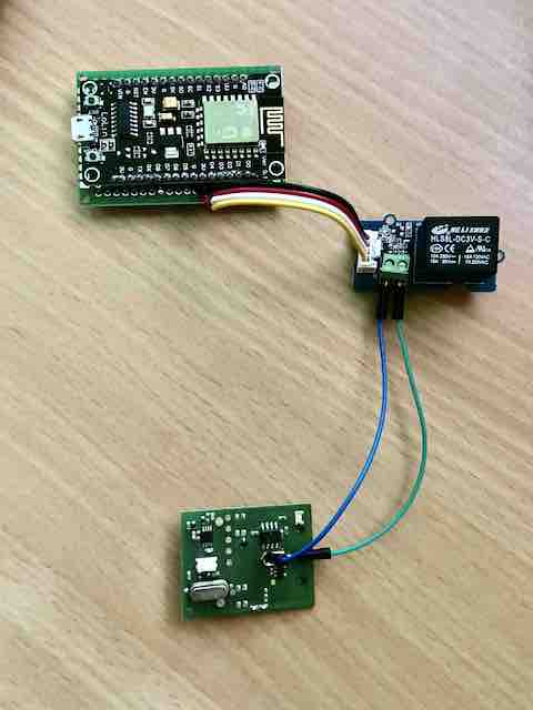
All we need is an ESP8266, a 3V relais and a remote control to open the garage door. The relais is powered by the ESP8266 3V pin and it’s signal is attached to pin D1 (GPIO-5). The output of the relais is soldered to the control button of the remote control.
In order to keep the solution simple, we will make use of an IoT service/software : https://blynk.io/
‘Blynk’ is free for basic usage as long as you are ok with the limitations e.g. max 2 devices to control. For our project this is just fine.
We will start by creating a IoT Device within ‘Blynk’
- Login to the Blynk IoT Service and create a ‘Template’ e.g. ‘ESP8266’
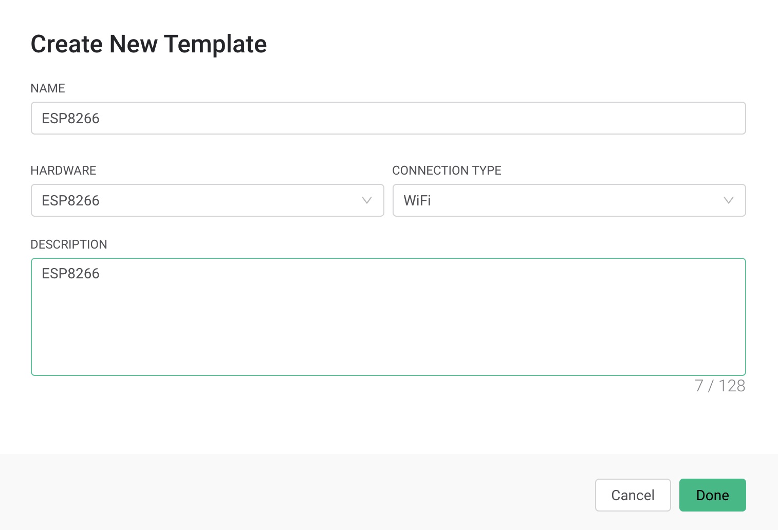
-
Next, while we’re in the template configuration, create 2 ‘Datastreams’ :
- Name: ‘Status’, Virtual Pin: ‘V0’, Data Type : ‘Integer’
- Name: ‘GarageDoor’, Virtual Pin: ‘V1’, Data Type : ‘Integer’
-
Now create a ‘New Device’ based on the template we created :
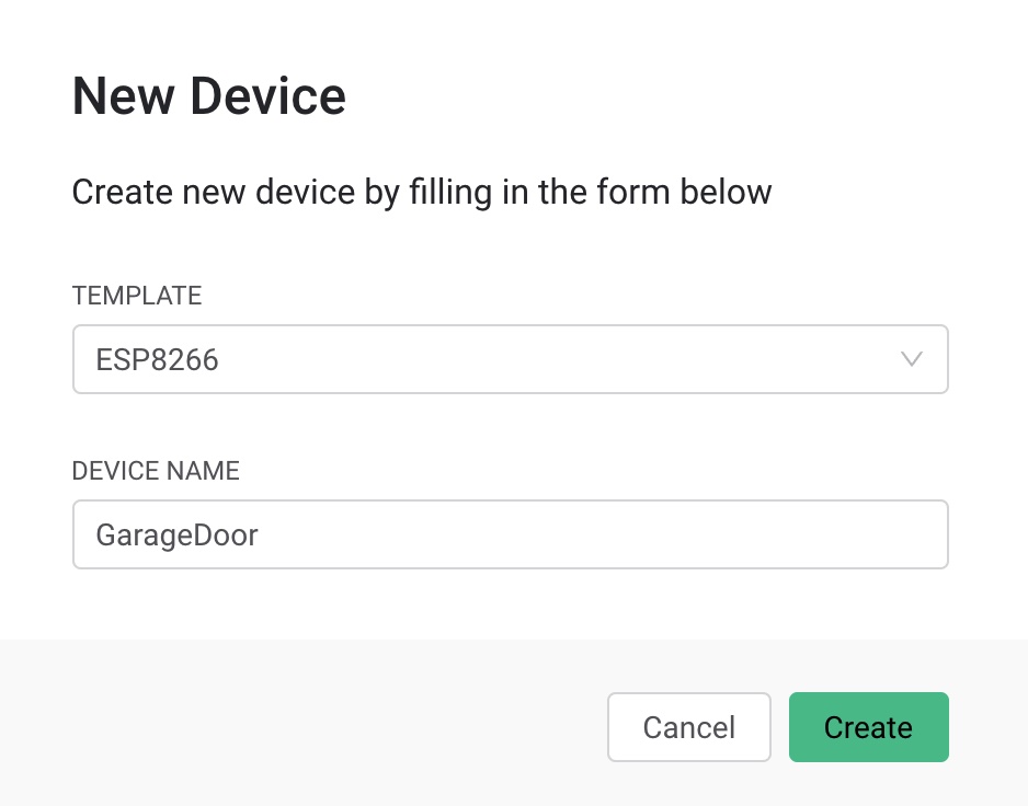
- Click on the popup to copy the code to the clipboard. This code contains the device info and a token to communicate with the Blynk platform. We will use these definitions later into our Arduino source code. This same info can also be found by clicking on the ‘Device info’.
Programming the ESP8266 using Arduino
- Open ‘Arduino’ and install the ‘Blynk’ Library (Tools - Manage Libraries…)
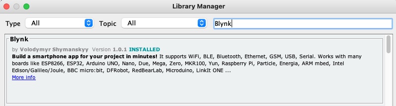
-
Open the Blynk example code : File -> Examples -> Blynk -> Blynk.Edgent -> Edgent_ESP8266
-
Copy/Paste the ‘Device Info’ obtained from the previous step to the beginning of the code
-
Complete the code with the additional logic to control the relais (see sample code below):
#define BLYNK_TEMPLATE_ID ""xxxxxxxxxx"
#define BLYNK_DEVICE_NAME "GARAGEDOOR"
#define BLYNK_AUTH_TOKEN "xxxxxxxxxxxxxxxxxx"

#define BLYNK_FIRMWARE_VERSION        "0.1.0"

#define BLYNK_PRINT Serial
// #define BLYNK_DEBUG

#define APP_DEBUG

// Uncomment your board, or configure a custom board in Settings.h
//#define USE_SPARKFUN_BLYNK_BOARD
#define USE_NODE_MCU_BOARD
//#define USE_WITTY_CLOUD_BOARD
//#define USE_WEMOS_D1_MINI

#include "BlynkEdgent.h"

// Use Virtual pin 0 for uptime display
#define PIN_UPTIME V0
#define RELAY_PIN 5

BLYNK_WRITE(V1)
{
    int pinData = param.asInt();
    Serial.println("Received : ");
    Serial.println(pinData);
    if (pinData == 1) {
        Blynk.virtualWrite(V0, 1);
        Serial.println("Sending Status");
        digitalWrite(RELAY_PIN, HIGH);
        delay(2000);
        digitalWrite(RELAY_PIN, LOW);
        Blynk.virtualWrite(V0, 0);
    }
}

void setup()
{
    Serial.begin(115200);
    delay(100);
    pinMode(RELAY_PIN, OUTPUT);
    delay(2000);
    digitalWrite(RELAY_PIN, LOW);
    // Start connected devices
    BlynkEdgent.begin();
}

void loop() {
    BlynkEdgent.run();
}
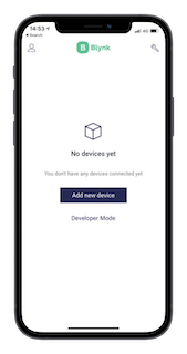
Configure the device using the ‘Blynk’ app on the smartphone
Open the app and add a new device using ‘Connect to Wifi’:
- Click on ‘Ready’ and the app will scan for a Wifi access-point exposed by the ESP8266.
- Click on join to connect
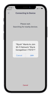
- Select your preferred Wifi access-point to be used by the ESP8266
- Now the device should be configured (stored to flash) and ready to communicate with the Blynk IoT Cloud service (if you want you can check the device log using the Arduino serial monitor)
Create a Mobile Dashboard
- Open the Blynk.App
-
Switch to Developer Mode (configure key at the top)
- Click on ‘+’ and add a ‘Led’
- You can drag it around, resize and position it as you want
-
Click on the ‘Led’ and select the DATASTREAM : ‘Status (v0)’
- Add a ‘Button’
- Click on the ‘Button’ and select the DATASTREAM : ‘GarageDoor(v1)’
You can play around and customize the interface (see example below) :
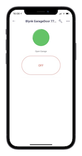
Now, when you hit the BUTTON, you should see the LED colour change and the relais should be activated which should result in a signal on the remote control to open the garage. The fact that the LED was turned of again means that the communication was successful as this action was performed by the Arduino code.